Pic circuits
Viewed products
-

On-off sequence of three relays with a push button
On-off sequence of three relays with...
On-off sequence of three relays with a push button
On-off sequence of three relays with a push button, microcontroller PIC 12F675.
Data sheet
| Design | Schema and circuit |
| View | No display |
| Supply voltage | 5 Volts |
| Electronic | Digital |
| Photo | No |
More info
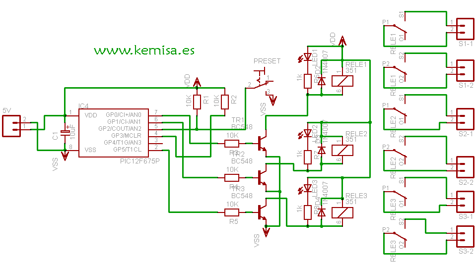
This small, but practical circuit is based on a microcontroller PIC 12F675.
The circuit works like this. Each time we press the push button, we turn on one relay and we turn off the others. Also, when we stop empowering the circuit, our microcontroller remembers its last position.
If we have left on, for example, the relay number two, when we empower the circuit again, the microcontroller will turn on the relay number 2 again. If we press the button once the relay number two will turn off and the relay number three will turn on.
If we press it again, the relay number three will turn off and the relay number one will turn on, and so on.
The .hex program that we provide you with has to be saved on a microcontroller PIC 12F675, the one we’ve used for this project.
When we save the microcontroller PIC 12F675 and we use it for the first time, we’ll have to press the button various times, until the first relay is activated, in order that the counter circuit and the PIC’s intern eeprom function correctly.
Once when we activate the relay, it will repeat the on-off cycle in sequence undefined number of times.
The wiring diagram
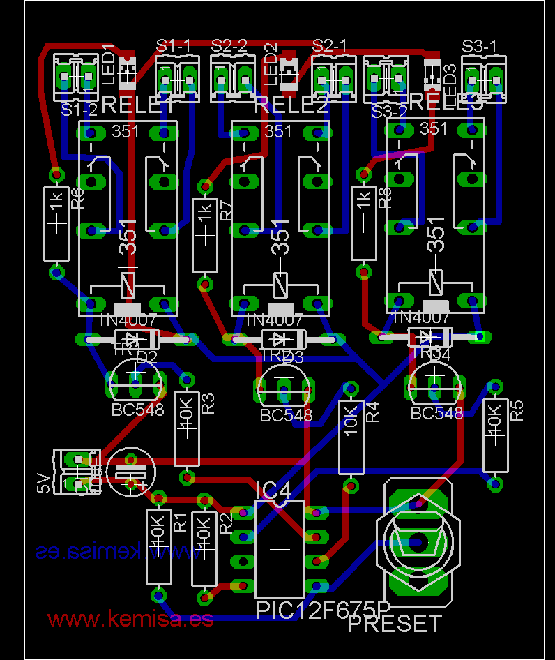
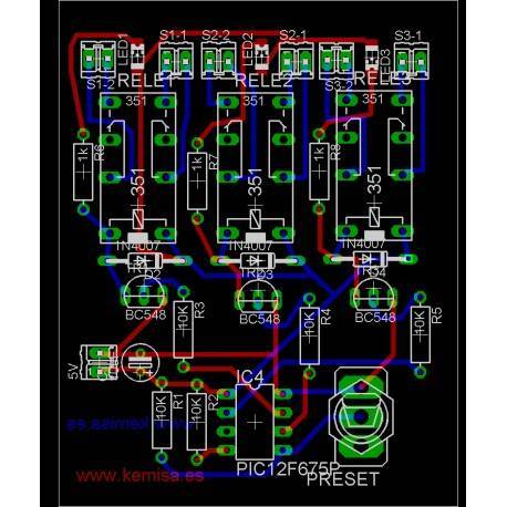
The circuit board.

The scheme and the circuit board should be in the same folder and they should have the same name, you should only change the extension to .sch for the scheme and to .brd for the circuit board, this way both of them will be recognized and associated by Eagle.
The file to download is compressed, to extract it, you should enter a password: www.kemisa.es
If you do not know how to program microcontrollers click here.


