Pic circuits
Viewed products
-

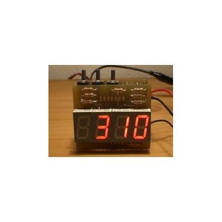
Digital clock with pic
Digital clock with pic 16F84A.
Data sheet
| Design | Schema and circuit |
| View | Display |
| Supply voltage | 5 Volts |
| Electronic | Digital |
| Photo | No |
More info
This circuit is based on a Dan Matthews’s project of the digital watch, published by the Microchip house.
Fortunately and thanks to the Denis Crawley, the original program for the PIC (Programmable Interruptions Controller) 16C54 has been adapted and it can be used with the more current PIC, the 16F84A, preserving the same circuit.
We have made certain hardware modifications on the circuit, making it even simpler.
We have also added an extra energy source with the battery; in case that the light goes out, currents exact time is not lost.
This circuit is very small, and therefore we can use it as a clock on a bedside table or as an office clock without it using up too much space.
The printed circuit board which we have prepared consists of two panels placed in a “sandwich”; in some cases, the routes are placed quite close together so you should pay attention while you are making a printed circuit and doing the welding.
First we’re going to take a look at the original circuit.
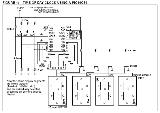
The circuit consists of the PIC, the displays, the quartz oscillator, several resistances and the adjust switches.
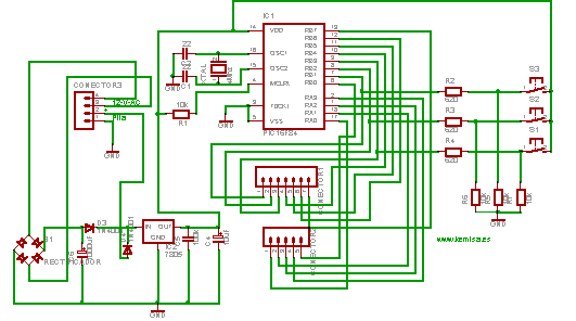
We suggest this other circuit. It is made of two superimposed panels.
On one of the panels we place the visualization: the displays.
On the other one we put the rest of the components, all of them, except the transformer and the battery.
This would be the scheme of the panel number one.
The circuit board.
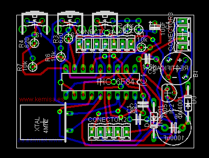
We have designed a third connector (connector number three, up on the right), leaving you the possibility to include the transformer and the battery on the third panel. We haven’t designed this last panel.
The rectifier and the condenser C6 (1000uF) go to the “bottom” face. Note that the name and the value go the other way around.
Now, let’s have a look at the panel 2 scheme, the one with the visualization of the displays.
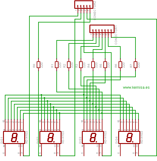
We have two connectors to interconnect the main panel, the panel number 1, with the displays. The panel number 2 design has been based on the width of the displays. Each display is 12 millimetres wide
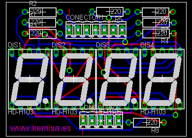
Real measures are 53x38 millimetres, which actually is a little bit more than what the displays occupy.
Remember that the scheme and the circuit board should be in the same folder and they should have the same name, you should only change the extension to .sch for the scheme and to .brd for the circuit board, this way both of them will be recognized and associated by Eagle.
Some important things to consider:
We have removed the original design transistors (2N5401) and the resistors that were placed at their bases. With this, we have simplified the design, but the resistors R1 to R8 should not be less than 150 ohms. With the 220 ohm resistors and the “kingbright sc52-11srwa” we have managed more than sufficient display brightness so as to see in a luminous ambient.
If you are going to use the clock on the bedside table, it would be advisable to raise the resistors’ value so that the clock wouldn’t bother you in the darkness. We have also removed the switch that connected the MCLR pin of the integrated circuit with the ground.
The switch sets the hour at 12:00, which is the default time that you see when the clock is turned on.
The file to download is compressed, to extract it, you should enter a password: www.kemisa.es
The actual code program version is V1.
The .hex code is a program that you have to engrave in the microcontroller 16F873A, which is necessary for the circuit to function.
If you do not know how to program microcontrollers click here.

